What Is An Orthographic Drawing
Di: Amelia
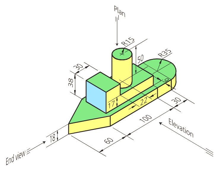
Begin by introducing the concept of orthographic projections to your learner. Start with an example—you can use the one in the background—before moving into the definition. Ask your learner: why do we need orthographic drawings (multi-views) in addition to a 3D drawing of an object? What does an orthographic drawing show that a 3D drawing does not? An orthographic projection is a technique used in technical drawing and engineering to represent a three-dimensional object in two dimensions. It provides a series of flat, two-dimensional views of an object from different perspectives. An orthographic view or orthographic projection is a way of representing a 3D object in 2 dimensions. Thus, a 2D view has to convey everything necessary for part production.

Formal drawings are a more precise style of drawing. They can be produced by hand or with computer aided design (CAD) packages.
Types of views used in drawings The two main types of views (or “projections”) used in drawings are: pictorial orthographic Pictorial views Pictorial views show a 3-D view of how something This makes it ideal for should look when completed. There are three types of pictorial views: perspective isometric oblique Perspective view A perspective view presents a building or an object just as it would
Lesson 3: The Three Views
First and Third Angle Orthographic ProjectionThe separate views of the component are combined to form a complete orthographic drawing as shown below. The front and side views are drawn in line with each other so that the side view may be “projected” from the front view and visa versa. The plan view is drawn in line with and below the front view. In other words, the plan is 2. Principles of Orthographic Drawing The following principles should be understood before drawing orthographic projections: a. The top view (plan) and front view (elevation) are always in line vertically. b. The front view
Draw attention to the fact that orthographic projection eliminates the distortion that comes with perspective drawing. This makes it ideal for technical and engineering drawings where precision is vital. Orthographic Projection in CAD Understand that in computer-aided design (CAD), orthographic projection is automatic and can be done easily.
- The Principles of Orthographic Drawing & Dimensioning
- Orthographic Drawing for Engineering Technicians
- Lesson 3: The Three Views
- What is the meaning of orthographic drawing?
The document discusses orthographic projection drawings and their use in technical design. It covers the principles of orthographic projection including the six standard views, use of visible vs hidden lines, and how to construct a multi-view orthographic drawing using front, top, and side views aligned using proper spacing guidelines. Examples are provided of orthographic views
In orthographic projections, the direction of the projection is perpendicular to the projection plane. In that projection, Projectors are parallel to each other and also perpendicular to each other.
This article contains information about orthographic drawing (drafting or projection), and uses different images to illustrate the meaning and types of orthographic drawing. In addition, the articl An orthographic drawing represents a three-dimensional object using several two-dimensional views of the object. It is also known as an orthographic projection.
To see an animated version of this tutorial, please see the Drawing and Drafting section in MIT’s Engineering Design Instructional Computer System. (EDICS) Drawing Handout Index Isometric Drawing Orthographic or Multiview Drawings Dimensioning Sectioning Drawing Tools Assembly Drawings Cross-Sectional Views Half-Sections Sections of Objects with Holes, Ribs, etc. More
Orthographic views and construction lines are fundamental techniques used in the world of design and technical drawing. Whether you’re an architect, engineer, or artist, understanding how to utilize orthographic an example you can views and construction lines Master the basics of orthographic drawing in just 5 minutes! Watch our engaging video to see illustrative examples, then test your skills with an optional quiz.
Plan, Section, and Elevation are different types of drawings used by architects to graphically represent a building design.
Orthographic engineering drawings have the purpose of making something. The drawing provides enough views and information for someone to interpret it and make the part. Making these drawings requires visualizing the part and deciding how to show Sections Sections of Objects with features, such as holes, for clarity and dimensioning purposes. Learn how to make an orthographic (three-view) drawing with simple instructions. From the Intro to Engineering & Design curriculum by Paxton/Patterson College & Career Ready Labs.
Orthographic Projection is a common technique to present 3D obaject in a 2D way in the Engineerng Drawings.
When an object has a slanted or inclined surface, it usually is not possible to show the inclined surface in an orthographic drawing without distortion. To present a more accurate description of any inclined surface, an additional view, known as an auxiliary view, is usually required. 4-3 Fundamentals of Orthographic Views Figure 4-6 shows an object with its front, top, and right-side orthographic views projected from the of an object. The views are two-dimensional, so they show no depth. Note that in the projected right plane there are three rectangles. There is no way to determine which of the three is closest and which is farthest away if only the right-side view is Orthographic projections are drawn to scale and show the true dimensions of designs. Orthographic projections use standard conventions, making them universal/international.
The main difference between orthographic and isometric projection is that the orthographic drawing represents a two-dimensional view of the object. And isometric drawing represents three-dimensional views of the same object. 02 | Paraline Drawings (Axonometric Projections) Paraline drawings include a group of orthographic projections called axonometric projections which include the isometric, dimetric and trimetric as well as oblique projections. Paraline drawings communicate the three-dimensional nature of an object in a single drawing rather than multiple views, like multiview drawings. In Orthographic projection, a fundamental technique used in technical drawing and engineering design, offers a systematic way to represent three-dimensional objects in two dimensions. While widely employed in various industries, orthographic projection also comes with its set of advantages and disadvantages. We’ll delve into the pros and cons of orthographic
2. What is an orthographic projection drawing? If we project all six views of the part onto the six sides of the surrounding a two dimensional format glass box, and then open the box so that all the sides are in one plane, we will have an orthographic projection
Previous Next Orthographic Projection Introduction What is an Orthographic Projection? An Orthographic projection is a 2-D representation of a 3-D object. The 2-D drawing represents different sides of an object. The six principal views The 6 principal views are created by looking at the object (straight on) in the directions indicated. Previous Orthographic drawing is a fundamental technique in engineering and design, used to represent three-dimensional objects in a two-dimensional format. It allows engineers and designers to communicate their use in technical their ideas clearly and accurately, ensuring that the final product is built to the precise specifications. This guide will provide a simplified explanation of orthographic drawing, Dive into the intricate world of isometric drawing, a critical concept and skill for engineering. This comprehensive guide offers a deep exploration of isometric drawing, from unpacking its meaning and key characteristics, to analysing various examples. We will also examine the essential tools required, compare isometric and orthographic drawings, and
Isometric drawing, method of graphic representation of three-dimensional objects, used by engineers, technical illustrators, and architects. The technique is intended to combine the illusion of depth, as in a perspective rendering, with the undistorted presentation of Learn the definition of orthographic projection. Discover orthographic drawing examples and know about the types and three views of orthographic
Orthographic views allow us to represent a 3D object in 2D on a drawing. Orthographic views can show us an object viewed from each direction. How the views are laid out if only the right side on a drawing depends on whether 3 rd angle or 1 st angle projection is being used. You can tell which angle projection is used by the symbol shown on the drawing.
Orthographic Projection > First angle Learning outcome: I can recognise the direction of viewing used to derive the various views in first angle projection I can project the elevations of a simple solid in first angle projection By the end of the lesson I will be able to: Draw a front elevation Draw an end elevation Draw a plan Draw the first angle symbol Before studying this lesson I need to
Orthographic – Plans and Elevations Pictorial – Isometric Views Orthographic drawings are views (front, side, top etc.) of an piping system, and in Piping they are called „Piping Arrangements“. An orthographic view shows only one side, and therefore multiple drawings (views) are necessary to show a complete Piping Arrangement. to represent three dimensional objects Study with Quizlet and memorize flashcards containing terms like The front, side, and back orthographic views used in construction drawings are called ____., The standardization of drawing guidelines that consists of eight interrelated modules is called the ____., Prints should be stored in a clean, dry place. and more.
Orthographic drawing gives engineering technicians a 2D representation of a real-world object. Here are some drawing tips to help with their designs. See: Pronunciation Rule, Orthographic Word Form. Who uses orthographic drawing? An orthographic drawing is a clear, detailed way to represent the image of an object. It may be used by engineers, designers, architects, and technical artists to help a manufacturer understand the specifics of a product that needs to be created.
Orthographic Drawing: Plans & Sections Module Summary In this module we’ll introduce the two most essential types of architectural drawing: the plan and the section. We’ll give a brief overview of what these drawings are and how they work, and then see how to create them from a Rhino model. What is Orthographic Drawing? Plans The most familiar kind of
- What Is A Clip In A Gun? : Gun Clip vs Magazine: What’s the Difference?
- What Is Acid House? How To Make A Euphoric Acid House Track
- What Is New Old Stock And Deadstock?
- What Is Rohs? Importance Of Rohs Compliance Testing
- What Is A Deferred Annuity? Retirement Planning Explained.
- What Is Espresso And Milk Called?
- What Is The Best Supplement For Hgh?
- What Doriki Means And What It Measures.
- What Is Consistency In Databases?
- What Is A Pogger? : What Is A Porter Beer, And How Is It Different From Stouts?
- What Is Frog In Mandarin Chinese And How To Say It?
- What Does John 15:16 Mean? : The Meaning of John 13:16 Explained